
N2 TEA Laser Build – Part 3: Capacitor & Switch Math and Fab
[latexpage]
Capacitor & Switch Math and Fab
In Part 2, I showed you the core components. Now it’s time to prove with math that these components will actually generate a powerful pulse, and then design the two parts that achieve the nanosecond speed: the capacitor’s size and the Spark Gap’s structure, and get the design mostly in place for initial powerup and test.
⚠️ Triple-Threat Safety Imperative: READ THIS FIRST
THIS PROJECT INVOLVES THREE DISTINCT LETHAL/HARMFUL HAZARDS. DO NOT ATTEMPT REPLICATION WITHOUT ADVANCED HIGH-VOLTAGE EXPERIENCE AND PROPER VENTILATION.
- 1.
 Lethal High Voltage: The
  circuit is lethal. NEVER touch the circuit when power is applied. All components must be contained within a grounded, non-conductive enclosure with safety interlocks before operation.
 - 2.
 Harmful UV Radiation: The laser emits deep ultraviolet (
 ) light (around
  ). This radiation is invisible, damaging to the retina, and can cause skin burns. NEVER look into the beam or at the spark without certified UV-blocking eye protection.
 - 3.
 Toxic Ozone Production: The high-energy discharge generates ozone (
 ) gas (a toxic air pollutant). Operation must be limited to short bursts and always performed in a well-ventilated area or under forced exhaust.
Classroom Use: Replication in any educational setting requires direct, professional supervision and a fully interlocked safety enclosure system.
📐 The Capacitor Guarantee: Hitting $27.5 \text{ nF}$
The “Wow Factor” requires storing at least $20 \text{ nF}$. I calculated the total capacitance of my system using $C = (\epsilon_r \epsilon_0 A)/d$:
- Area ($A$): Two $5″ \times 7″$ plates give me $70 \text{ in}^2$ ($\approx 0.045 \text{ m}^2$).
- Result: The calculation yields: $C \approx \mathbf{27.5 \text{ nF}}$. This is exactly in the target range!
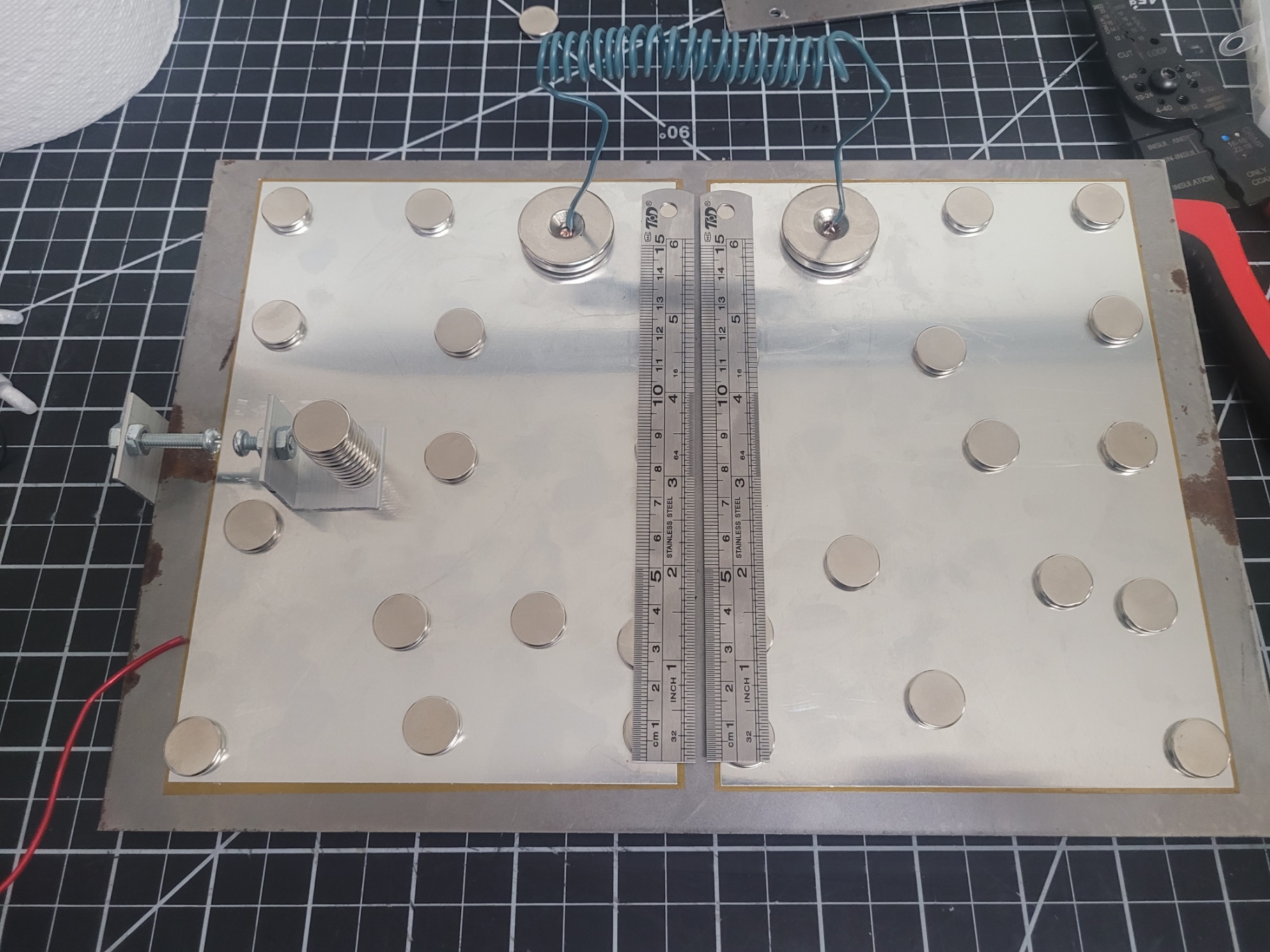
Here is the raw Cap Bank build from these specs, showing how i applied the adhesive kapton, etc…:
💥 The Channel: Blade Fixturing and Brush Contacts
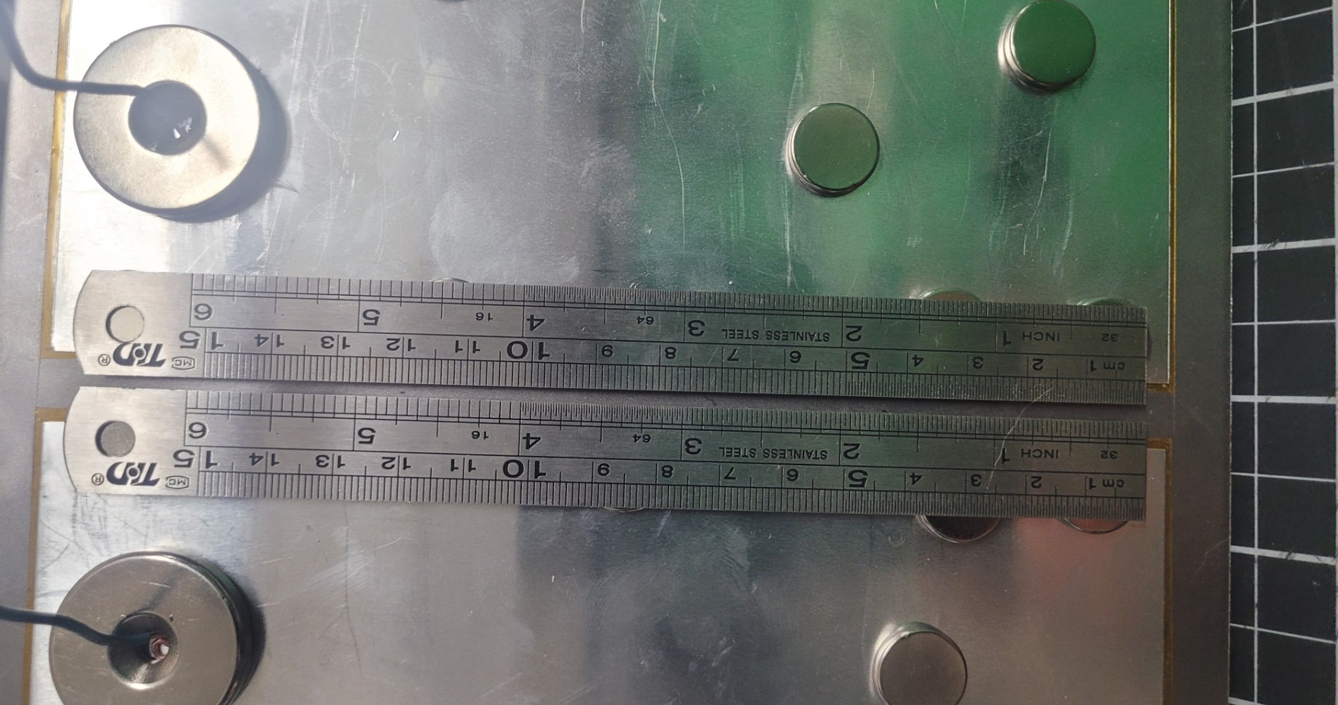
The two $6 \text{ inch}$ steel rulers must be held $1 \text{ mm}$ apart and have a perfect electrical connection.
- Electrical Contact: I’m going to try a magnet array to make electrical connection to the top plates.
- Structural Fixturing: I’ll use the same method above for the mechanical connection as well.
I may have to alter this design as this is the most critical, and finicky part of the device.
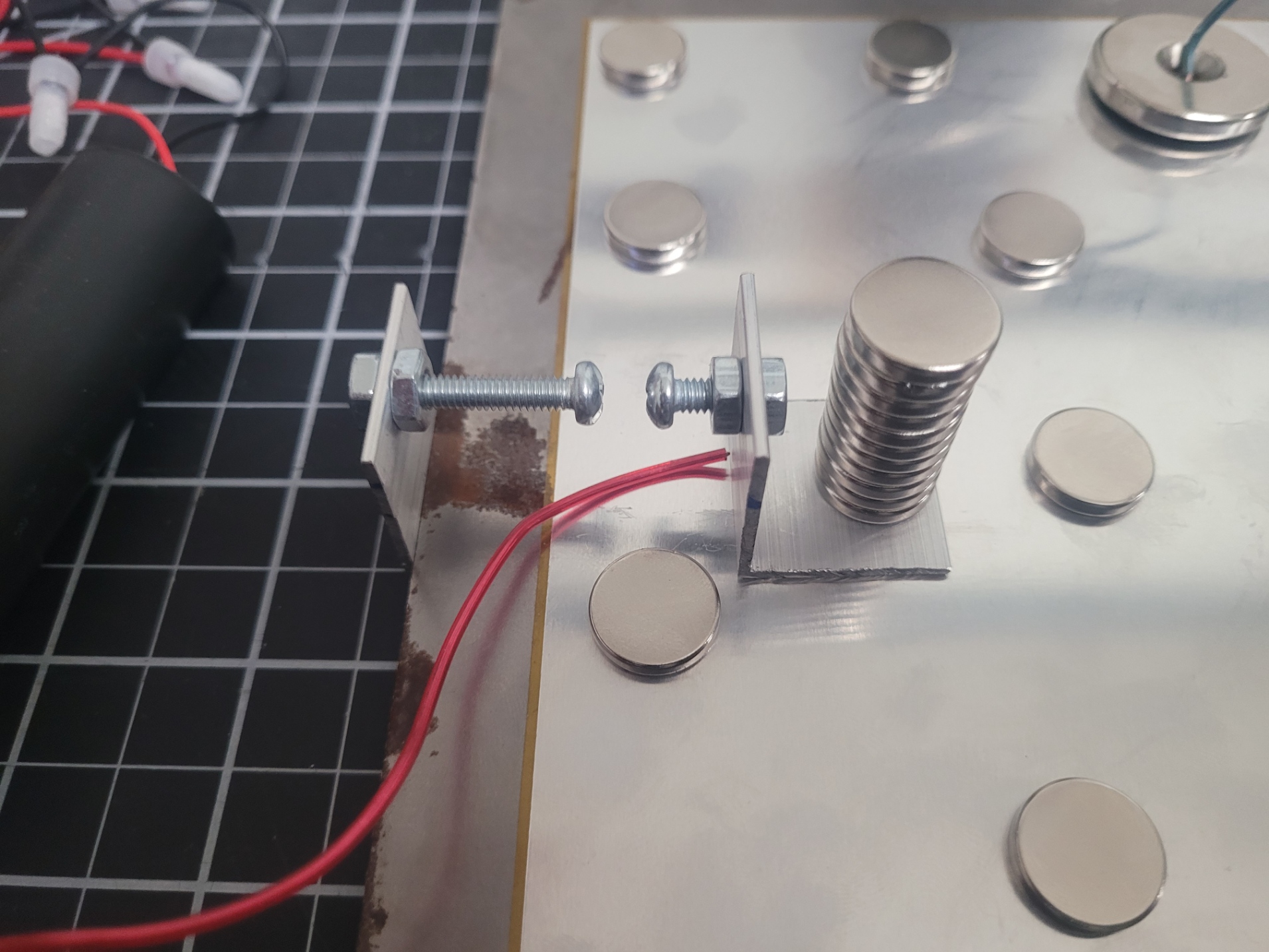
⚡ The Switch: Designing the Spark Gap
The Spark Gap (SG) is the high-speed switch. I’m designing it for low inductance and durability:
- Electrode Material: I will use machine screws.
- Adjustability: The SG can be adjusted by the screws and/or by sliding the SG top-plate side bracket as it is just held in place with a stack of magnets.
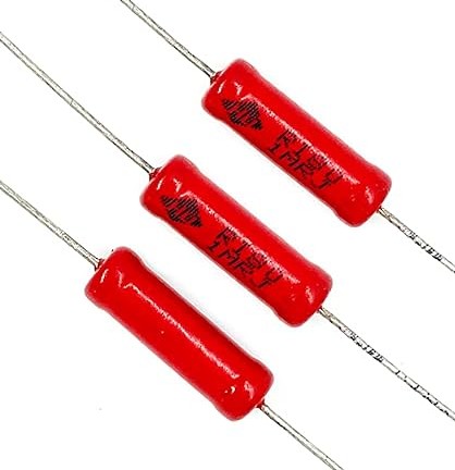
NOTE: We also need resistors for the project and they are on the way.. hi-voltage 1MΩ for charging and for making a discharge feature for safety.
Stay tuned for Part 4!