President Dwight D. CB Base Resto-Mod Part 2
🔬 Part 2: Cracking the Case – Board ID, PLL, and Hidden Mods!
You can find President Dwight D. CB Base Resto-Mod Part 1 here.
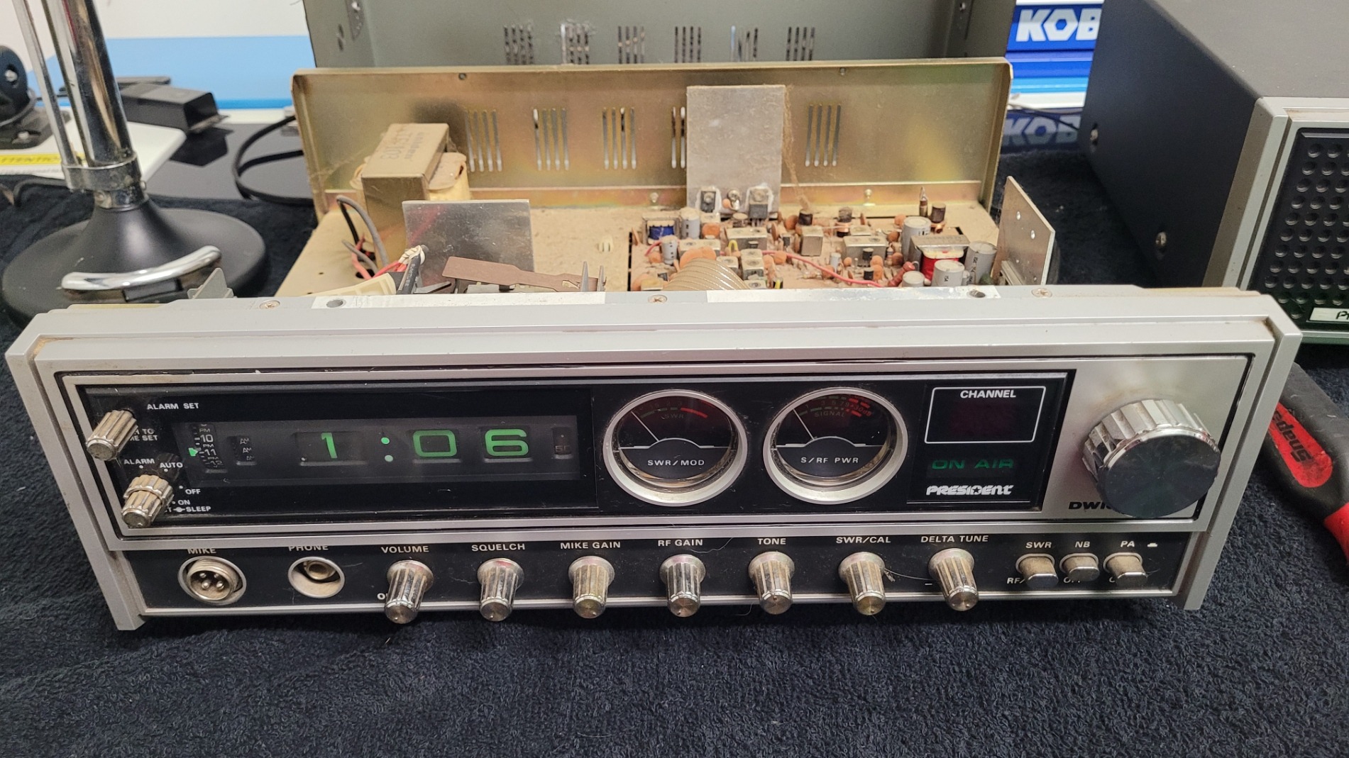
The moment of truth arrived! I cracked open the President Dwight D. base station, ready to confirm the board type and uncover the history hidden beneath its metal shell. This radio had clearly seen some enthusiastic use—and definitely some meticulous user-installed modifications.
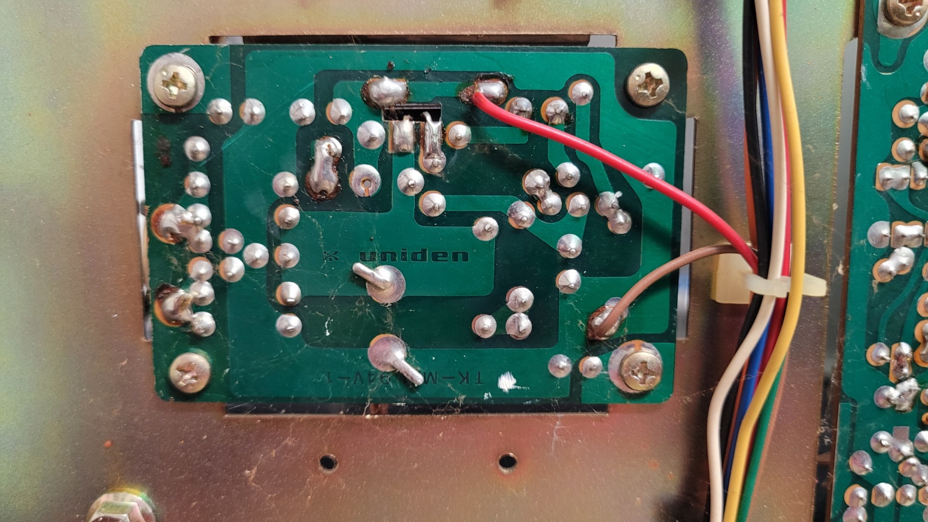
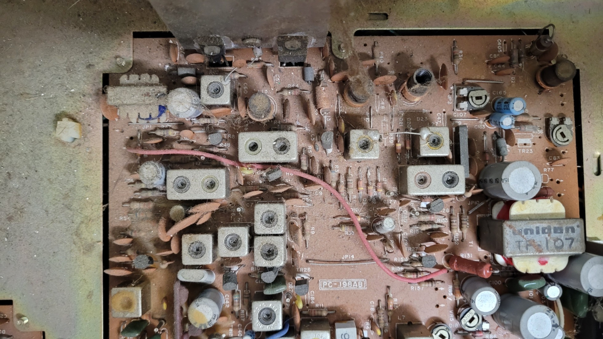
1. Board ID: Confirmed PC-198AB Chassis
The first priority was identification. I quickly confirmed the board version: it’s the classic PC-198AB chassis, distinguished by its use of the well-known Uniden D858 PLL chip!
This chip and board combination immediately told me something important: this specific rig was from the era of radios highly favored by enthusiasts for modifications.
2. A Modder’s History: Three Core Findings
This radio was definitely not stock! The moment the lid came off, it was clear a previous owner had a serious interest in getting more performance and functionality out of the rig. I found evidence of three major, non-factory interventions:
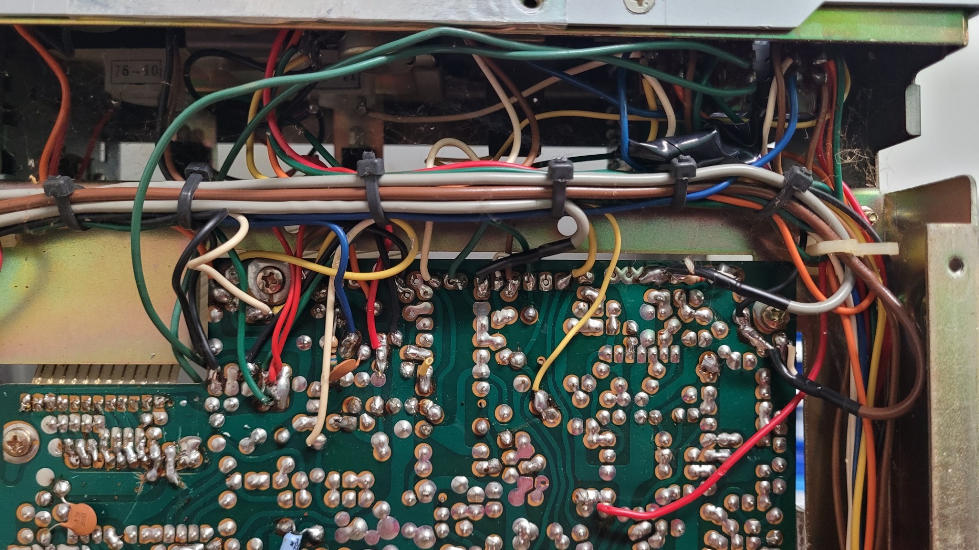
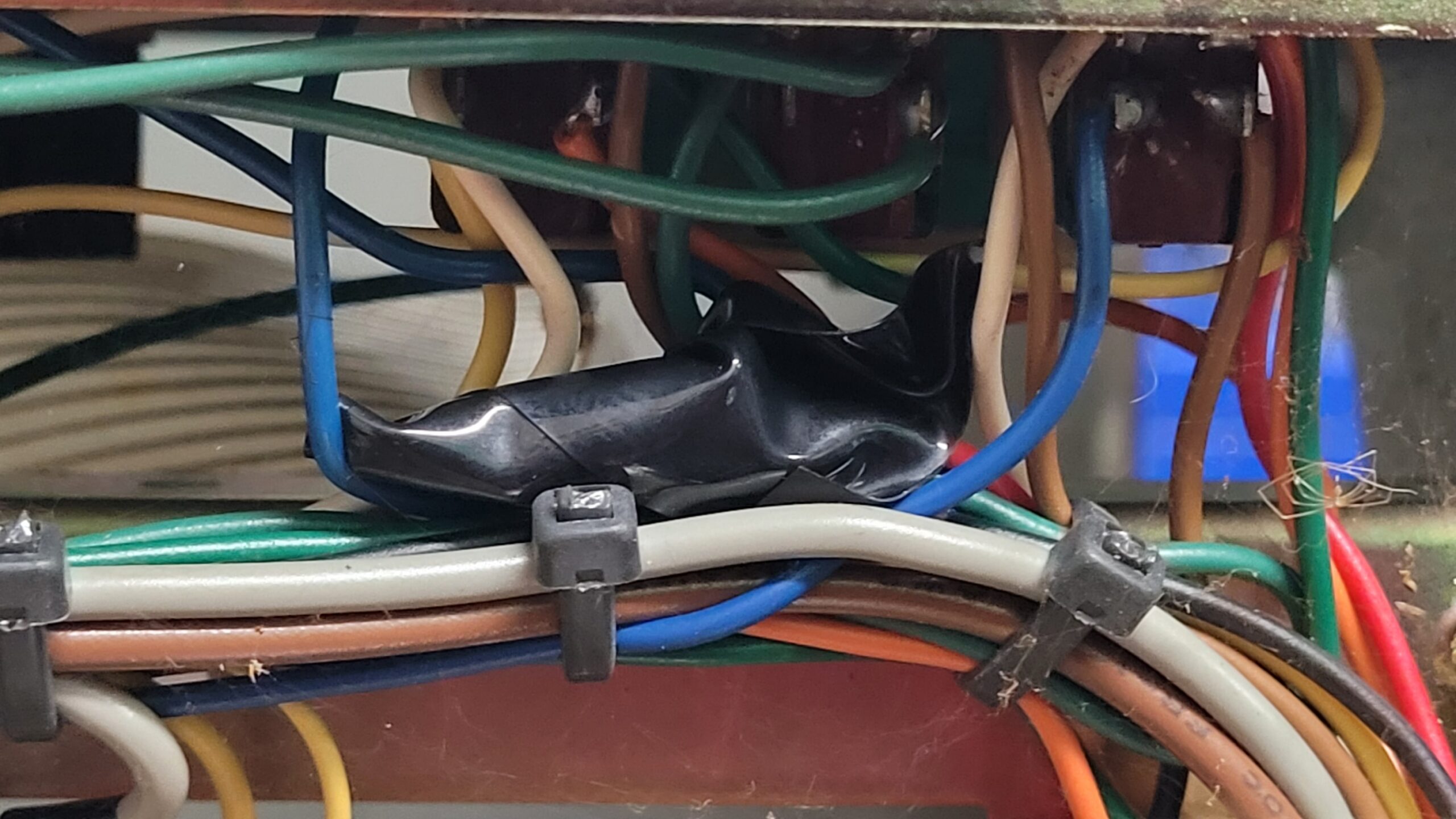
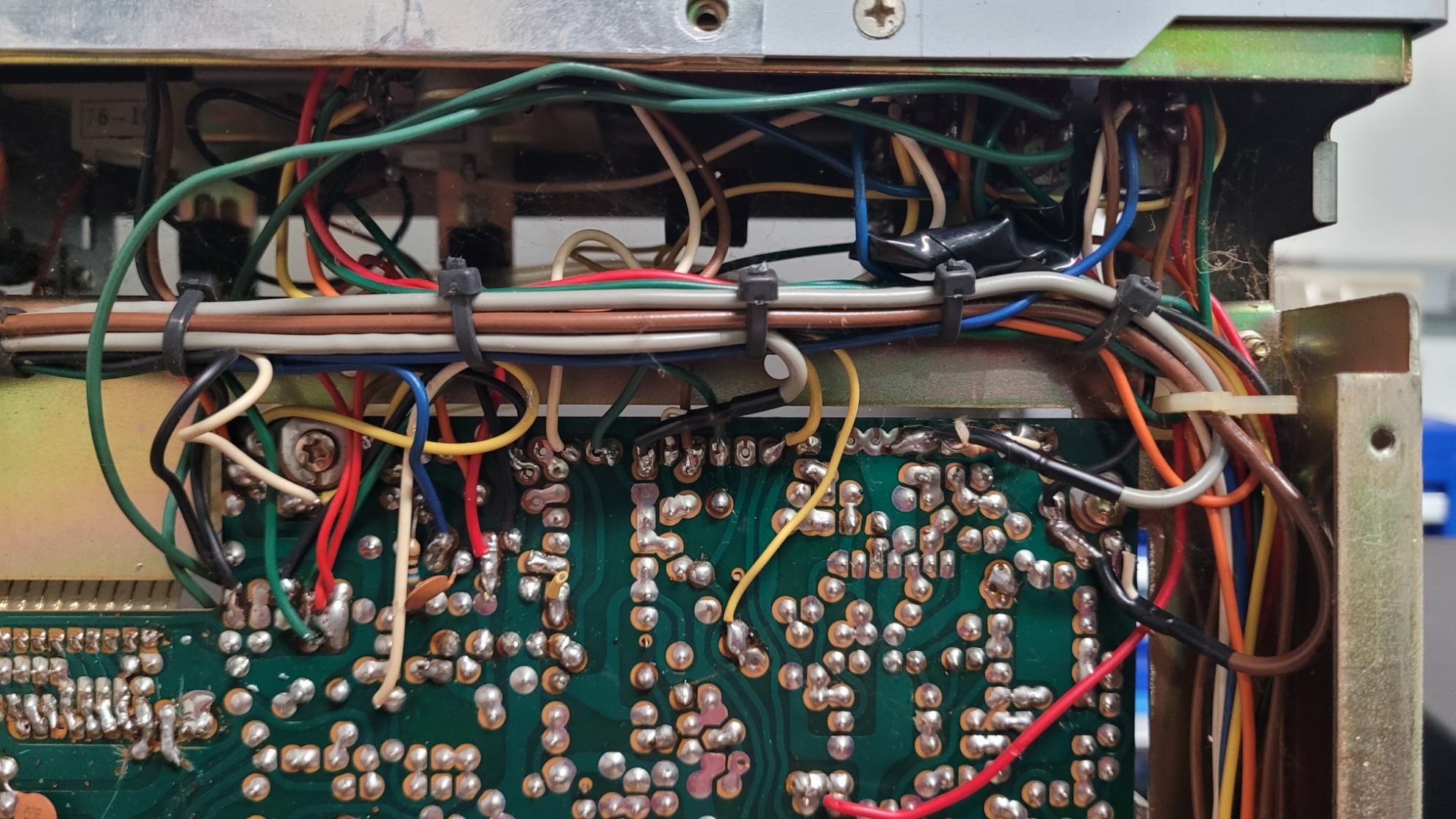
Mod A: Channel Expansion (The PLL Wiring) 📈
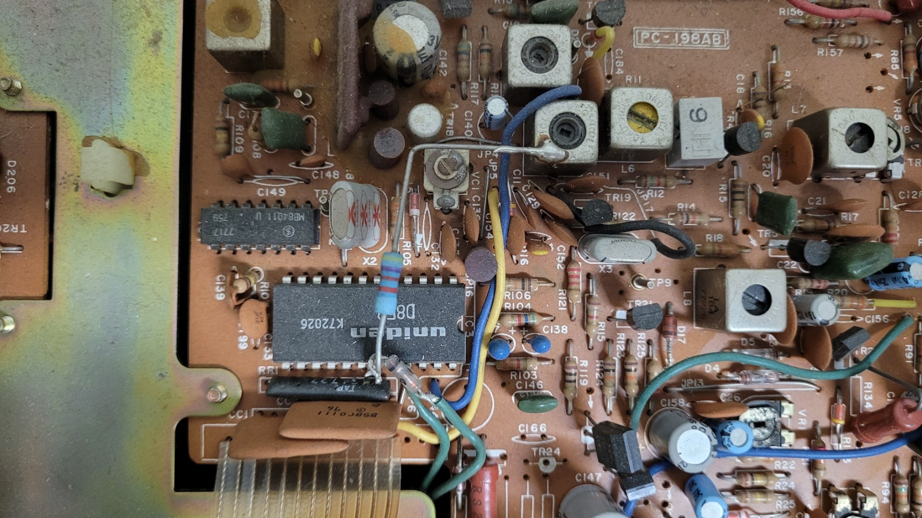
This is the most visually obvious and complex modification. It dramatically extends the radio’s frequency capability.
-
Evidence: Multiple colored wires (green, blue, yellow, and brown) are soldered to the pins of the D858 PLL chip, and a large resistor bridges two adjacent points.
-
Hypothesis: This is the classic technique used to alter the PLL’s digital programming code, enabling the radio to access expanded channels (often referred to as “upper” and “lower” bands) outside of the standard 40 CB channels.
-
Next Step: I strongly suspect those two green wires visible near the PLL are running to the front panel, having repurposed the Noise Blanker and or CB/PA switches to control the band switching. Tracing this will be critical in Part 3!
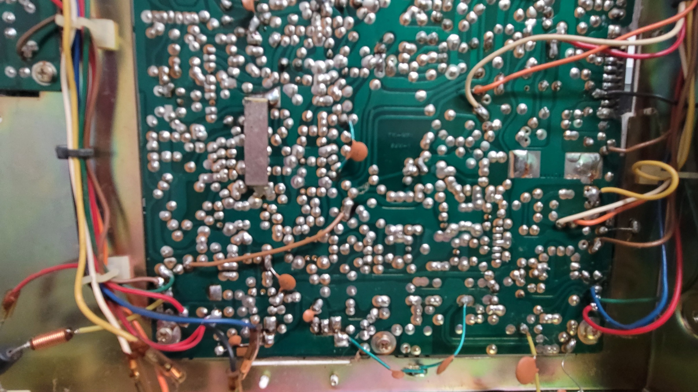
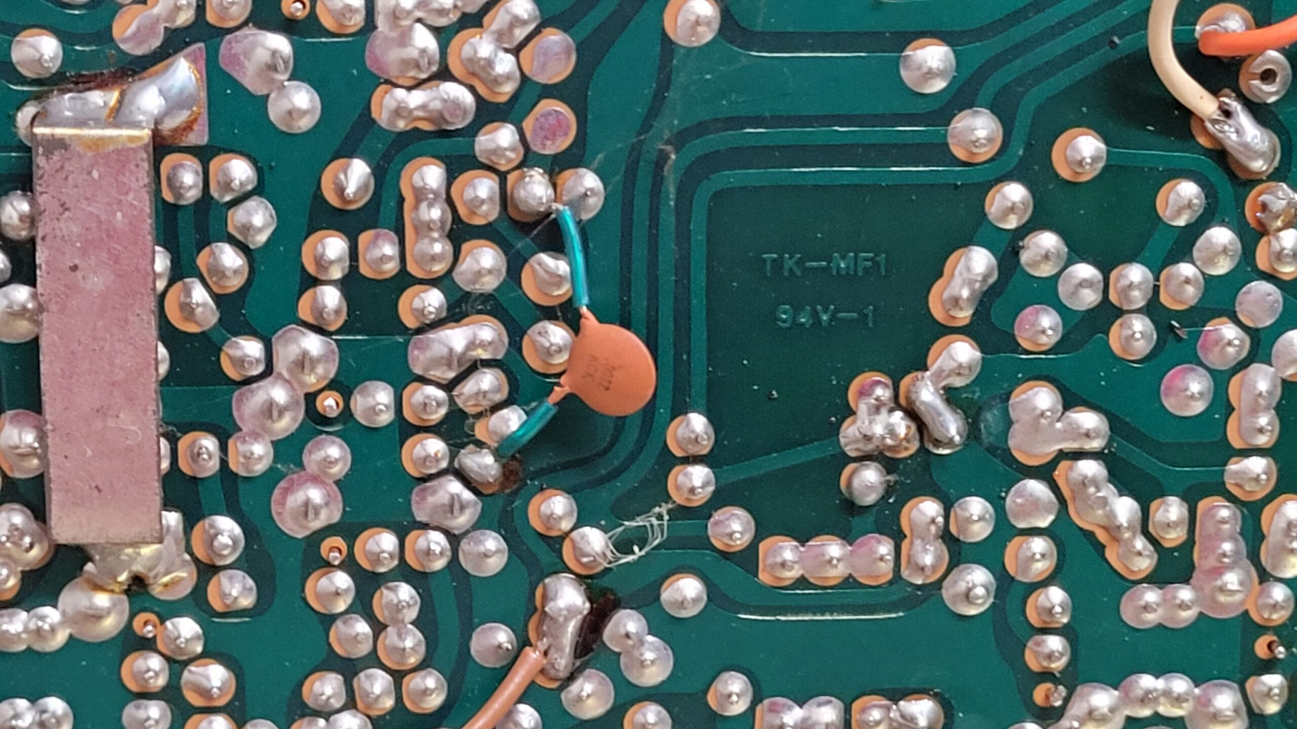
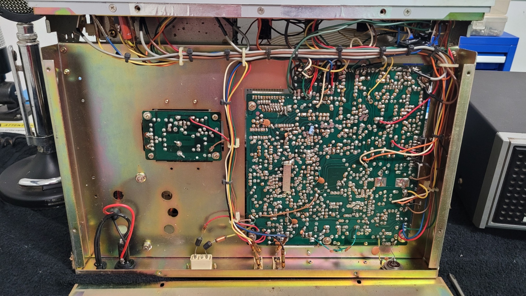
Mod B: Unlocked Clarifier (TX/RX Track) – Capacitor Tweak 🔗

Flipping the board over revealed a precise adjustment made near the frequency control circuits.
-
Evidence: Two distinct disc capacitors (identifiable by their shape and insulation) are hand-soldered across two points on the foil side of the board in the Clarifier (Delta Tune) circuit area. These are user-installed components, not factory parts.
-
Hypothesis: This setup enables the Clarifier Unlocked (TX/RX Track) feature. The capacitors are strategically placed to tailor the frequency response of the Voltage Controlled Oscillator (VCO), ensuring the transmit frequency tracks the receive frequency consistently as the Clarifier knob is adjusted. This is a crucial mod for talking to others on those expanded channels.
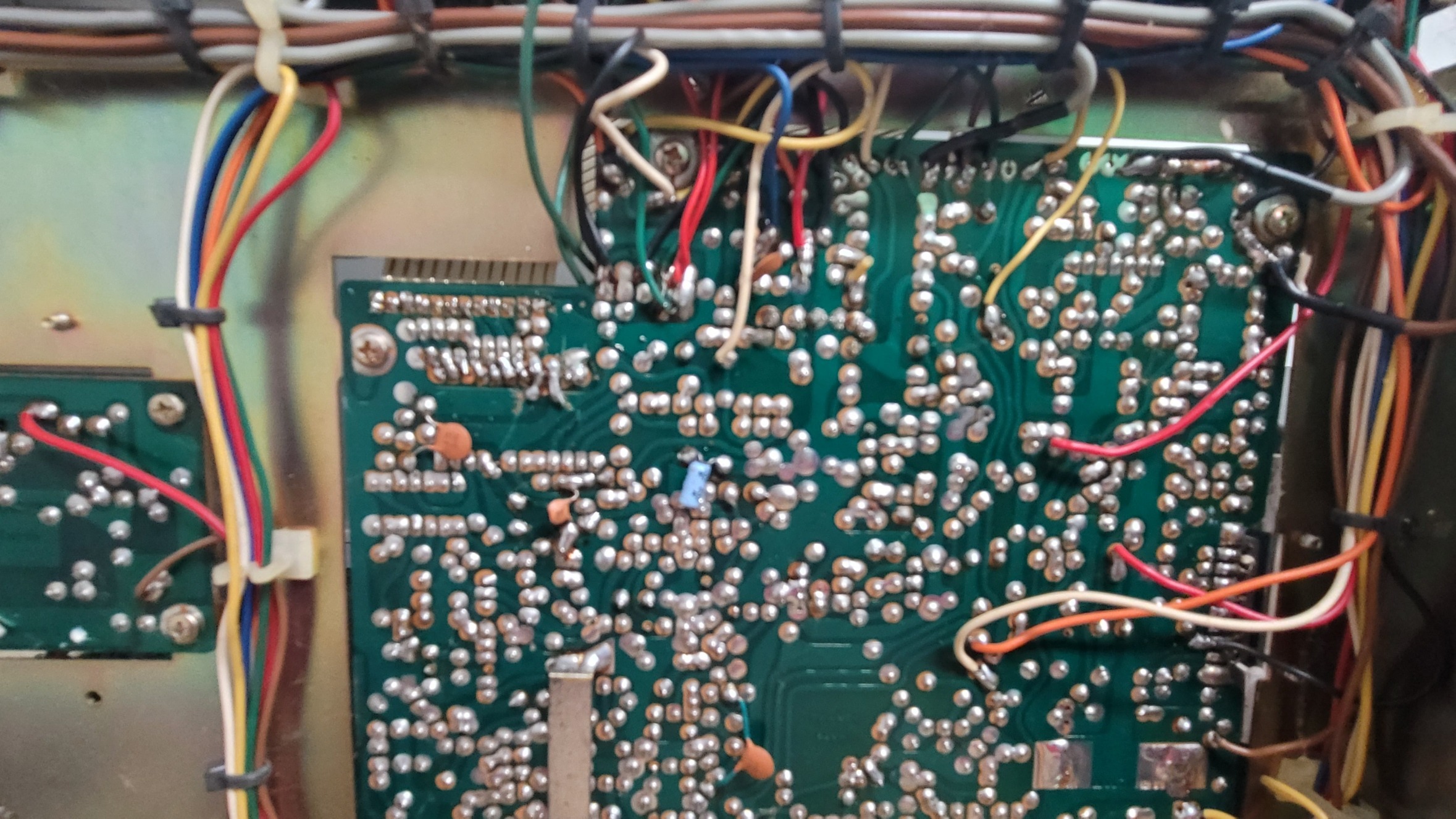
Mod C: Modulation/Audio Circuit Tweak 🔊
More non-factory wiring was found near the rear of the board, suggesting a focus on audio performance.
-
Evidence: Several additional, loose wires (red, white, and black) are hand-soldered to the foil side of the board in the area where the main factory harness connects. This spot is typically near the Automatic Modulation Control (AMC) and audio circuits.
-
Hypothesis: This is likely an attempt to enhance the modulation (make the audio louder/punchier) by tweaking the gain or modifying the modulation limiter to achieve greater swing on the air.
🎬 What’s Next: The Road Ahead
The President Dwight D. is turning out to be a fascinating piece of radio history! It was clearly a highly customized workhorse.
My next steps for Part 3 will be to clean up the unit and dust it all off and tidy it all up after a close visual inspection. Then verify reference service manuals, diagrams, schematics, etc… to officially confirm the switch repurposing, and to clarify which suspected mods are in fact mods or repairs. I will decide later which of these modifications to preserve or remove in the interest of stability and clean performance, check and replace any suspect caps, and/or begin the critical restoration of the classic Astatic D-104 TUP9 microphone. For now I’m going to get it all figured out and working. More to follow!
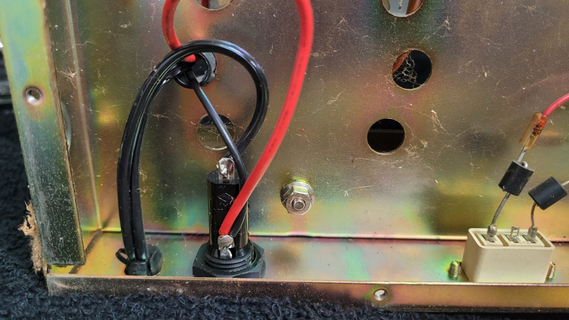
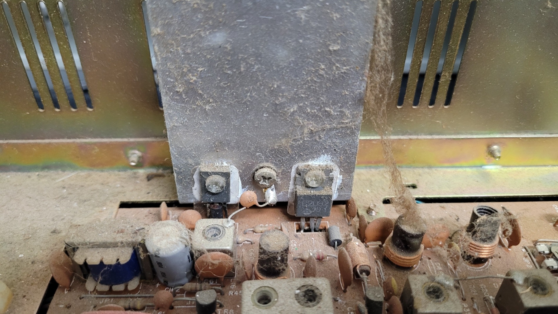
Here are more pics: