

President Dwight D. CB Base Resto-Mod Part 3
🔬 Part 3: Documentation and Cleanup Complete – The Final Blueprint
(This post directly follows the investigative findings detailed in President Dwight D. CB Base Resto-Mod Part 2.)
This post marks a crucial phase transition! We executed the Initial Restoration (Cleaning) and the rigorous Technical Investigation (Data Collection) using the equivalent schematics. We now have the definitive blueprint showing the nature and intent of the modifications, but the final confirmation of function awaits the test bench in Part 4. The need for component replacement will be determined only after exhaustive initial performance tests.
1. 🧹 Step One: Initial Restoration and Deep Clean
Before trusting our visual inspection or beginning the technical research, stabilization was necessary. This initial phase was purely physical cleaning—no components were removed, replaced, or adjusted.
Deep Cleaning the Base Station
-
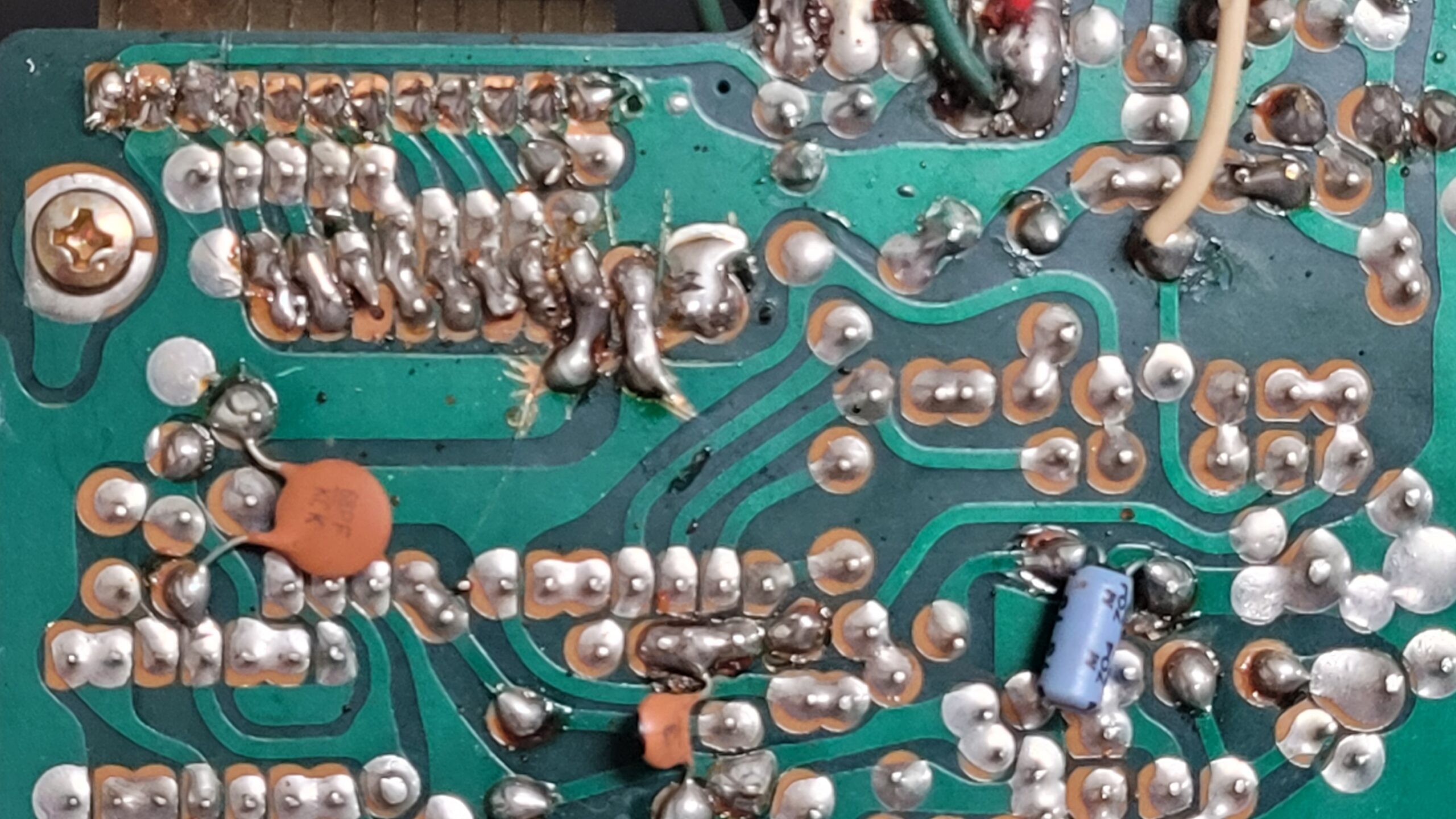
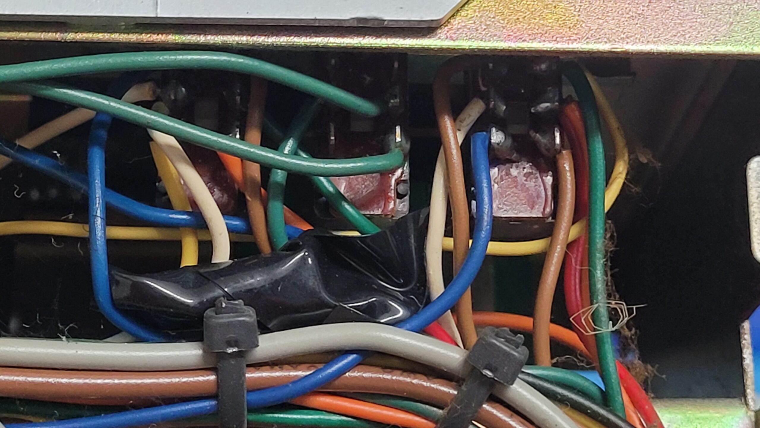
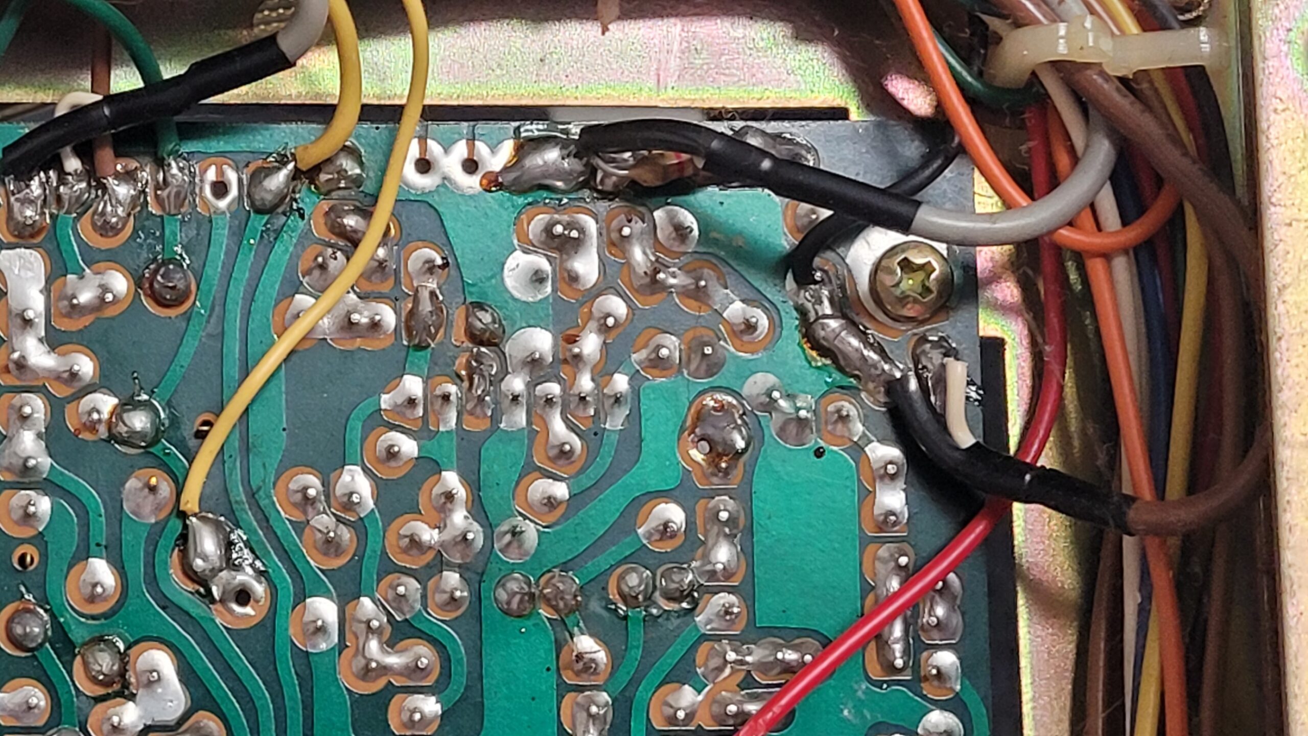
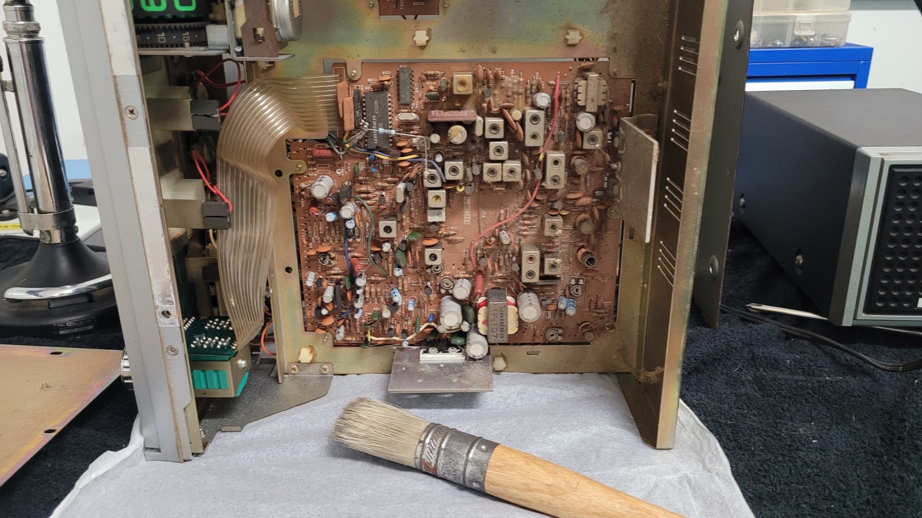
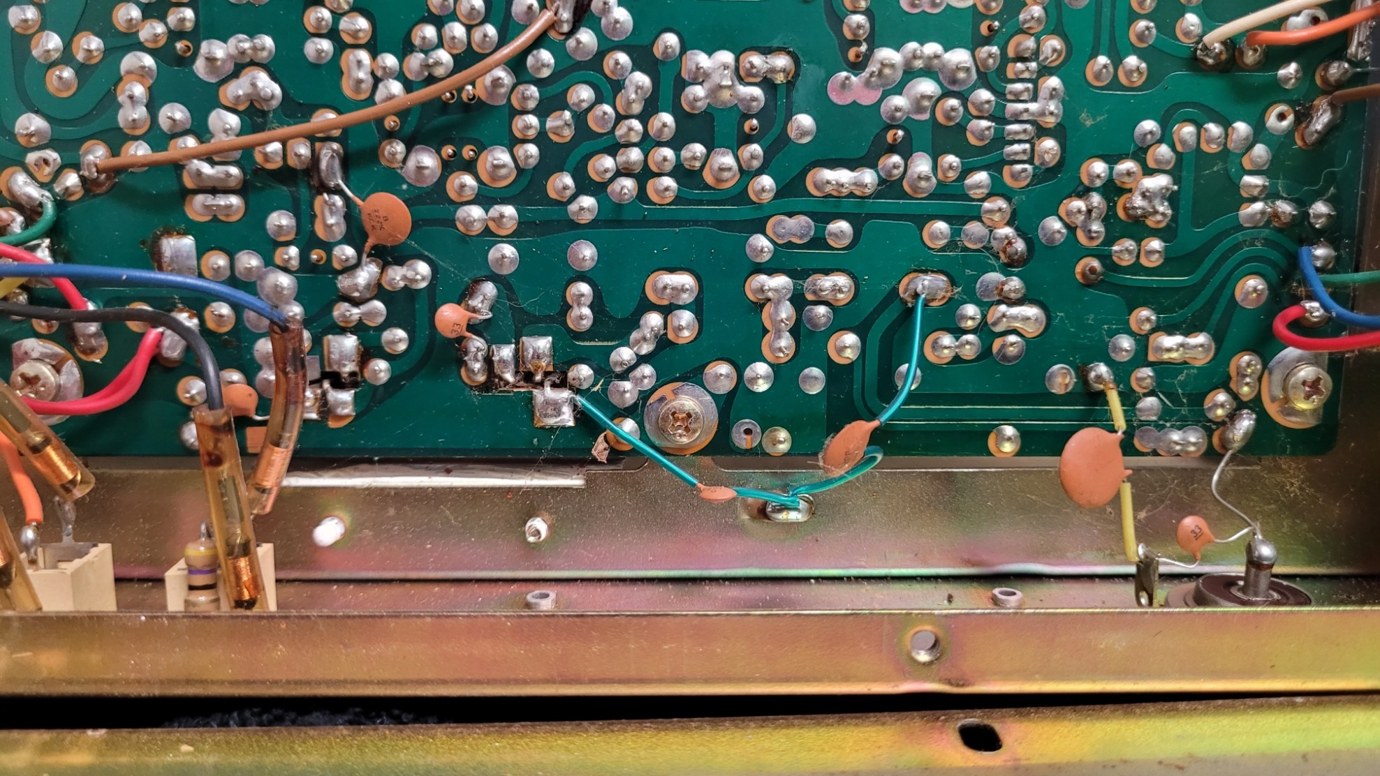
Dust Removal: We used compressed air and soft brushes to carefully remove the thick, accumulated dust and grime from the main PCB, heat sinks, and chassis interior. This simple act drastically improved component visibility.
-
Chassis and Controls: The exterior chassis, faceplate, and knobs received a thorough wipe-down with mild cleaners.
-
Results: The cleaning was a success! We now have clear sight lines across the entire board, making the wiring easier to trace.


2. 📖 Step Two: Technical Investigation and Functional Analysis 🗺️
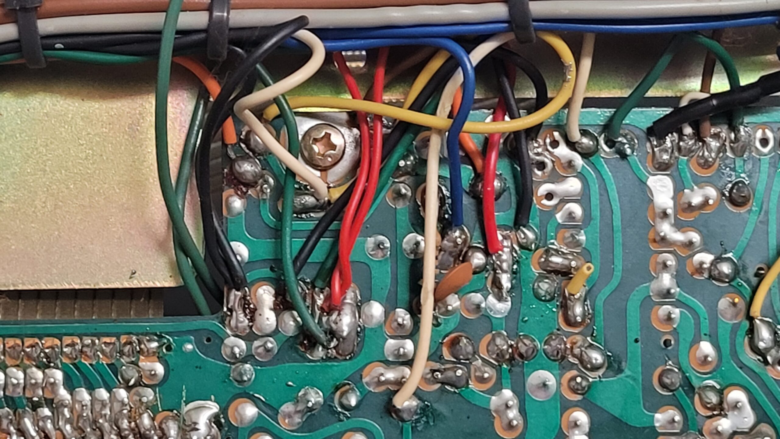
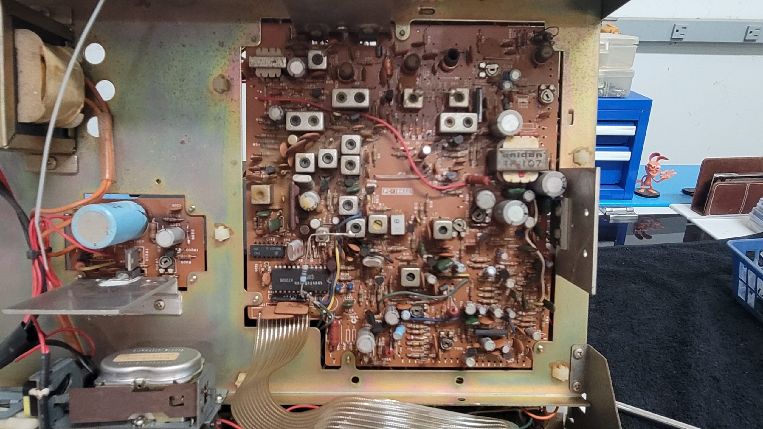
Using documentation for the equivalent PC-198AB chassis, we performed a side-by-side analysis of the schematics against the physical wiring. This gave us the necessary insight to understand the function and purpose of the mods, which we will now validate with testing.
The Cobra 29XLR used 2 boards. The main one was a PC-198AA and the other was a PC-241AB 1/2. Looks like most of the docs for the XL29 with PC-198AA. This should give us some clarity.
- Cobra 29XLR Owner Manual
- Cobra 29XLR OEM Schematic
- Cobra 29XLR SVC MAN Schematic
- Cobra 29XLR Service Manual
The Four Highly Probable Modifications We Now Identify:
| Mod # | Hypothesis | Purpose & Next Step (Validation) |
| A | Frequency Expansion | PURPOSE CONFIRMED: Wiring alters the PLL’s BCD pins for extended channel selection. VALIDATION: Part 4 will confirm if the bands are stable and correctly programmed. |
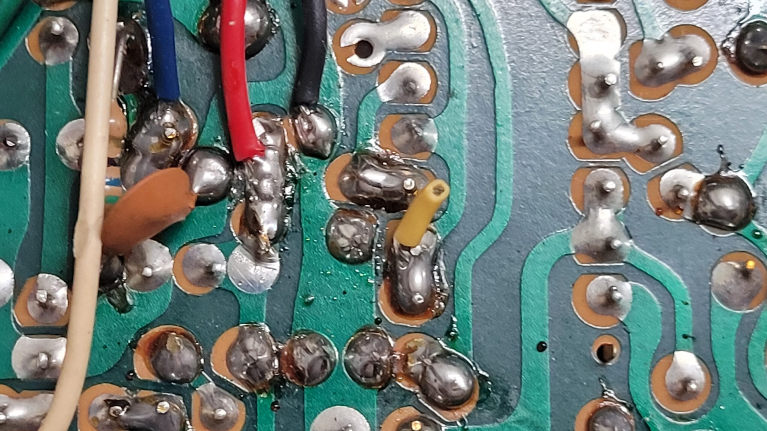
| B | Clarifier Track | PURPOSE CONFIRMED: The disc capacitors stabilize the TX/RX frequency track in the VCO circuit. VALIDATION: Part 4 will test if the transmit frequency follows the receive frequency across the sweep. |
| C | Variable Power | PURPOSE CONFIRMED: Wiring intercepts the Automatic Power Control (APC) circuit. VALIDATION: Part 4 will confirm if the repurposed knob controls RF output power. |
| D | Audio/Modulation Tweak | PURPOSE CONFIRMED: Wires/soldering in the AMC circuit suggest the limiter is bypassed. VALIDATION: Part 4 will measure the modulation percentage to confirm if it swings beyond stock limits. |
The Repurposed Switch Solved!
We successfully traced the wires for the Channel Expansion mod (Mod A) and found they lead to the Noise Blanker (NB) switch. We now know which factory function was sacrificed, ready for functional testing.
3. 🎬 What’s Next: The Testing Phase
The investigation is complete, and we have the full restoration blueprint. Now, we prepare for the physical work and the critical validation step.
-
Part 4 will involve the rigorous performance testing of the currently configured radio, after replacing the failing peripherals (cords, jack). This testing will be the final step to CONFIRM the functionality of all four mods.
-
The decision to install newer components, remove mods, or keep the rig “as is” will be made only after testing reveals a failure or performance shortfall. We are sticking to the mantra: Document, Test, and Only Then Decide to Replace.